UL 14B-2008 pdf download.Sliding Hardware for Standard, Horizontally Mounted Tin-Clad Fire Doors.
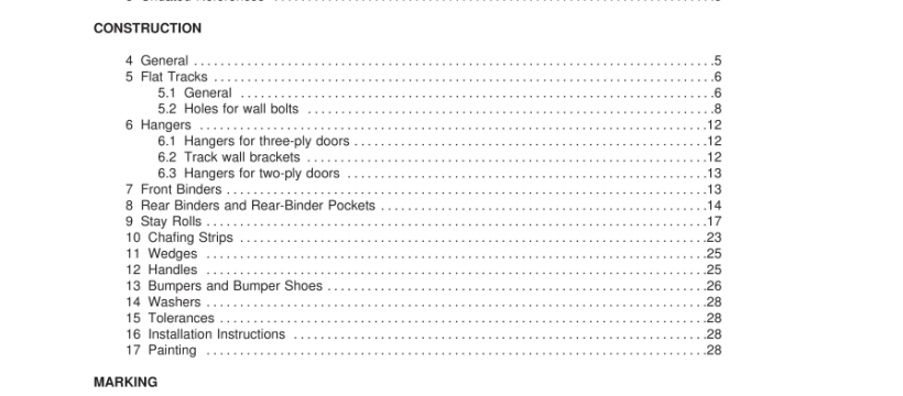
3 Undated References 3.1 Any undated reference to a code or standard appearing in the requirements of this standard shall be interpreted as referring to the latest edition of that code or standard. CONSTRUCTION 4 General 4.1 Each complete set of hardware for horizontally sliding tin-clad fire doors is to include: a) One track, length equal to twice the width of the opening plus 21 in (530 mm) drilled for wall bolts. b) Two hangers for openings 6 ft (1 .8 m) and less in width; three hangers for openings wider than 6 ft (1 .8 m), and bolts for attaching hangers to door. c) Two front binders for openings 8 ft (2.4 m) and less in height; three front binders for openings in excess of 8 ft (2.4 m); one rear binder and rear-binder pocket with strip for openings of 7 ft (2.1 m) and not more than 1 0 ft (3.1 m) in height; two rear binders and rear- binder pockets with strips for openings exceeding 1 0 ft (3.1 m). d) One stay roll with attachment bolts required for the form of sill used. e) One bracket for each track bolt. f) Two half-oval chafing strips for back of door; two flat strips for front of door opposite of half- oval strips; bolts for fastening above strips together through door; length of strips to be 4 in (1 02 mm) less than width of door. Doors exceeding 8 ft (2.4 m) in height require three chafing strip assemblies. A rear-binder pocket strip to be employed in lieu of the top oval chafing strip on doors equipped with two rear-binder pockets. g) One strip 5 in (1 27 mm) less than width of door to take wear of stay roll; and wood screws for attachment. h) One wedge with screws for attachment. i) Handles with bolts and screws for attachment. j) One front bumper and one back bumper. k) Four bumper shoes and screws for attachment; each bumper shoe is made in two pieces. l) Washers for all wall bolts. m) Instructions for installation.
5.2 Holes for wall bolts 5.2.1 Holes for wall bolts shall be 1 3/1 6 in (20.6 mm) in diameter and located so that a wall bolt shall be placed directly opposite each hanger when the door is closed and so that front and back bumpers can be attached to the end bolts. See Figure 5.1 for details. 5.2.2 The location of bolt holes and the number and location of hangers are shown in Table 5.1 and Table 5.2. 5.2.3 The space (A) in Table 5.1 shall always be on the side of the door opening toward which the door closes. This is the lower end when the track is inclined. 5.2.4 Doors for openings in excess of 6 ft (1 .8 m) in width shall require three hangers. 5.2.5 When the size of the door opening is not specified in Table 5.1 or Table 5.2, the proper interpolation shall be made for the bolt spacing in accordance with 5.2.6.
9 Stay Rolls 9.1 A stay roll, Type No. 1 , for a three-ply tin-clad door shall be a U-shaped member and shall be made of flat-rolled steel, 2-1 /2 in (64 mm) wide and 1 /2 in (1 2.7 mm) thick, as shown in Figures 9.1 and 9.2 or 9.5. 9.2 The side next to the wall shall be 6-3/4 in (1 72 mm) long above the sill, the upper 2-1 /2 in (64 mm) being offset 1 /2 in (1 2.7 mm) to receive the angle-shaped strap for fastening it to the wall. 9.3 The side bearing the roller shall be long enough so that the center of the roller is 7-1 /2 in (1 91 mm) above the sill. The inside distance between the sides of the guide shall be 3-3/8 in (86 mm). 9.4 A guide shall be fastened against the wall by an angle piece made of 2-1 /2 by 1 /2 in (64 by 1 2.7 mm) steel. The side of the angle on the face of the wall shall be 8-1 /2 in (21 6 mm) long, the end being offset 3/4 in (1 9.1 mm) and provided with a 1 3/1 6 in (20.6 mm) hole 6 in (1 52 mm) from the end of the angle. The opposite side shall be 1 0 in (254 mm) long, a 9/1 6 in (1 4.3 mm) hole for a 1 /2 in (1 2.7 mm) eye-bolt being provided 8-1 /4 in (21 0 mm) back from the face of the wall. The angle piece shall be drilled and countersunk for a 1 /2 in (1 2.7 mm) countersunk machine screw with which it is fastened to the guide. A 1 /2 in (1 2.7 mm) eye-bolt, 7 in (1 78 mm) long, shall be provided for attaching the end of the angle in the door opening to the 3/4 in (1 9.1 mm) wall bolt. 9.5 When roller guides are bolted together through the wall, a U-shaped strap shall be provided. UL 14B-2008 pdf download.
UL 14B-2008 pdf download
