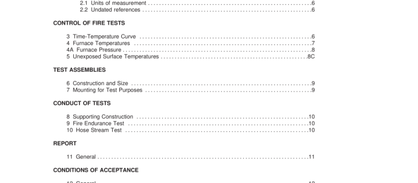
UL 10B-2008 pdf download.Fire Tests of Window Assemblies.
4 Furnace Temperatures 4.1 The temperatures of the test exposure shall be the average temperature obtained by a minimum of three thermocouples and no fewer one thermocouple per 1 5 square feet of test assembly exposed to the furnace symmetrically disposed and distributed to show the temperature near all parts of the test assembly, see Figure 4.1 . The thermocouple assembly is to consist of a thermocouple protected by a sealed porcelain tube having a 3/4 inch (1 9.1 mm) outside diameter and 1 /8 inch (3.2 mm) wall thickness or, a base-metal thermocouple, protected by: (1 ) sealed 1 /2-inch (1 2.7-mm) wrought-steel or wrought-iron pipe of standard weight or (2) Inconel 600 series schedule 40 pipe (0.8 inch OD / 0.6 inch ID, 20 mm OD / 1 5 mm ID). The end of the thermocouple assembly is to be initially located 6 inches (1 52 mm) from the exposed face of the test assembly or from the construction in which the door assembly is installed. During the fire exposure, if the movement of the test sample causes the sample’s distance to the end of the thermocouple assembly to vary, the end of the thermocouple assembly is to be reset to 6 inches (1 52 mm) at intervals not exceeding 1 0 minutes during the first 30 minutes of the test. Thereafter, the intervals are to be increased to not more than 30 minutes. Revised 4.1 effective February 1 6, 201 8 4.2 The temperatures are to be recorded at intervals not exceeding 1 minute. 4.3 The accuracy of the furnace control is to be such that the area under the time-temperature curve, obtained by averaging the results from the thermocouple readings, is within 1 0 percent of the corresponding area under the standard time-temperature curve for fire tests of 1 hour or less duration or during the first hour of multi-hour tests, 7.5 percent in the first 2 hours of multi-hour tests, and within 5 percent for tests exceeding 2 hours in duration.
4A Furnace Pressure Added 4A effective February 1 6, 201 8 4A.1 Furnace pressures are to be read at intervals not exceeding 1 minute. 4A.2 The neutral plane within the test furnace shall be established prior to the initiation of the fire test. Such pressure shall remain constant or increase to maintain the neutral plane upon initiation of the fire test. Control of the furnace pressure is to be established beginning no later than 5 minutes after the start of the test and is to be maintained throughout the remainder of the fire test. 4A.3 The vertical pressure distribution within the furnace is to be measured by at least two pressure-sensing probes separated by a minimum vertical distance of 6 ft (1 .8 m) inside the furnace for furnaces with a minimum vertical dimension of 1 0 ft (3.05 m). Minimum vertical separation between pressure probes is to be reduced proportionally for furnaces with an internal dimension less than 1 0 ft (3.05 m). 4A.4 The pressure-sensing probes are to be as shown in either Figure 4A.1 or Figure 4A.2. The probes are to be located so that the center line of the sensing holes are positioned 6 ±1 in (1 52 ±2.5 mm) from the surface of the exposed face of the test assembly and a minimum of 1 8 in (457 mm) from the edges of the furnace. The probes are to be positioned horizontally in the furnace without a change in vertical elevation of the probes or tubing within the furnace.
6 Construction and Size 6.1 The construction and size of the test door assembly, consisting of single doors, doors in pairs, special-use doors (such as Dutch doors or double-egress doors), or multisection doors, shall be representative of that for which classification or rating is specified. 6.2 A floor structure shall be provided as part of the opening to be protected, other than where such floor interferes with the operation of the door. The floor segment shall be of noncombustible material and shall project into the furnace for twice the thickness of the test door, the anticipated deflection of the bottom bar of a rolling door, or to the limit of the frame, whichever is greater. 7 Mounting for Test Purposes 7.1 Swinging doors shall be mounted so as to open into the furnace chamber. 7.2 Sliding and rolling doors, other than horizontal slide-type elevator doors, shall be mounted on the exposed side of the opening in the wall closing the furnace chamber. 7.3 Horizontal slide-type elevator doors shall be mounted on the unexposed side of the opening in the wall closing the furnace chamber.UL 10B-2008 pdf download.
UL 10B-2008 pdf download
