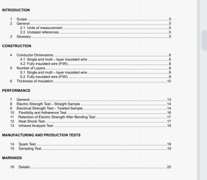
UL 2353-2021 pdf download.Single- and Multi-L ayer Insulated Winding Wire.
3.2 BASIC INSULATION – Insulation that provides basic protection against the risk of electric shock. 3.3 CLEARANCE – The shortest distance between two conductive parts measured through air. 3.4 CREEPAGE DISTANCE – The shortest path between two conductive parts measured along the surface of the insulation. 3.5 INSUL ATING LAYER – A single, concentric thickness of material that is detectable with an optical or mechanical measuring device. Enamel, bond coats, etc. are not considered insulating layers. See 1.2. 3.6 REINFORCED INSUL ATION – A single insulation that provides protection against risk of electric shock equivalent to double insulation under the conditions specified in the Standard for Information Technology Equipment – Safety – Part 1: General Requirements, UL 60950-1, the Standard for Medical Electrical Equipment, Part 1: General Requirements for Safety, UL 60601-1, or the Standard for Adjustable Speed Electrical Power Drive Systems – Part 5-1 Safety Requirements – Electrical, Thermal and Energy, UL 61800-5-1. Reinforced insulation is not required to be provided in one homogeneous piece. It may consist of several layers that cannot be tested as supplementary or basic insulation. 3.7 ROUTINE TEST – A test to which each individual sample is subjected during or after manufacture to verify that the sample complies with certain criteria. 3.8 SAMPLING TESTS – A test on a number of samples taken at random from a batch of winding wire.
3.8 SAMPLING TESTS – A test on a number of samples taken at random from a batch of winding wire. 3.9 SEPARABLE LAYERS – A construction that includes layers of insulation that may be separated in a non-destructive manner. 3.10 SUPPL EMENTARY INSUL ATION – Independent insulation applied in addition to basic insulation in order to reduce the risk of electric shock in the event of a failure of the basic insulation. CONSTRUCTION 4 Conductor Dimensions 4.1 Single and multi – layer insulated wire 4.1.1 When determining the conductor dimensions, tin or any other metal on the conductor is allowed to remain on the conductor and included in the measurement. For film insulated Magnet Wire, the solvent based enamels are to be removed prior to any measurements. Measurements of the diameter of a solid conductor are to be made by means of a machinist’s micrometer caliper having flat surfaces both on the anvil and on the end of the spindle and calibrated to read directly to at least 0.01 mm or 0.001 in, with each division of a width that facilitates estimation of each measurement to 0.001 mm or 0.0001 in. The maximum and minimum diameters at a given point on the conductor are each to be recorded to the nearest 0.001 mm or 0.0001 in, added together, and divided by 2 without any rounding of the sum or resulting average.
4.1.3 The total cross sectional area of the conductors in a stranded wire shall be at least equivalent to the minimum cross sectional area of the equivalent solid wire as noted in Table 4.1 for customary US AWG trade sizes, or calculated using the tolerances specified in Table 4.2 for wires constructed to the customary metric trade sizes and any other non-customary size. The unrounded average of two micrometer readings taken on at least five strands shall be used to calculate the total cross sectional area and compared directly with the minimum in the table for the purpose of determining whether the stranded wire does or does not comply with the requirement. For a stranded conductor made up of film insulated Magnet Wire using solvent based enamel coatings, the enamel coating shall be removed prior to measuring conductor diameters to determine cross sectional area. 4.2 Fully insulated wire (FIW) 4.2.1 When determining the conductor dimensions solvent based enamels are to be removed prior to any measurements. Measurements of the diameter of a solid conductor are to be made by means of a machinist’s micrometer caliper having flat surfaces both on the anvil and on the end of the spindle and calibrated to read directly to at least 0.01 mm or 0.001 in, with each division of a width that facilitates estimation of each measurement to 0.001 mm or 0.0001 in. The maximum and minimum diameters at a given point on the conductor are each to be recorded to the nearest 0.001 mm or 0.0001 in, added together, and divided by 2 without any rounding of the sum or resulting average.UL 2353-2021 pdf download.
UL 2353-2021 pdf download
