UL 69-2009 pdf download – Electric-Fence Controllers.
3 General 3.1 Units of measurement 3.1 .1 If a value for measurement is followed by another value in other units in parentheses, the second value may be only approximate. The first stated value is the requirement. 3.2 Undated references 3.2.1 Any undated reference to a code or standard appearing in the requirements of this standard shall be interpreted as referring to the latest edition of that code or standard. 4 Glossary 4.1 For the purpose of this standard the following definitions apply. 4.2 CONTINUOUS CURRENT OUTPUT – Output current which has a steady-state peak of 7.0 mA or more. 4.3 CURRENT PULSE – The current which flows during the time period in which 95 percent of the output energy of a single fence controller output waveform has been transferred to the load resistor. 4.3.1 DIRECT PLUG-IN CONTROLLER – An electric fence controller for indoor use only with a single output which employs a blade assembly on the enclosure for connection to the branch circuit. The controller may be provided with output wiring or wire binding screws intended for connection to solid wire. Not considered a direct plug-in power supply that is detachable from the electric fence controller. 4.3.1 added December 4, 201 3 4.4 ELECTRICAL BREAKDOWN – Occurs when a discharge bridges the insulation under test, reducing the voltage between the electrodes to zero or nearly zero.
4.5 EQUIPMENT GROUNDING MEANS – A lead or terminal, provided in the splice compartment of a permanently mounted fence controller, that is intended for connection to the branch circuit (supply) grounding conductor; or the grounding pin of an attachment plug of a 3-wire power supply cord, provided on a portable fence controller, that is intended for connection to the branch circuit (supply) grounding conductor. 4.6 FENCE TERMINAL – The output terminal that is not intended to be connected to earth ground. 4.7 LEAKAGE CURRENT – Any current that may be conveyed from accessible parts, other than the fence output terminals, to ground or to other accessible parts. 4.8 OUTPUT GROUND TERMINAL – The output terminal that is intended to be connected to the fence ground rod. 4.9 PEAK-DISCHARGE OUTPUT – Output current pulses that are unidirectional single impulses. 4.1 0 PERMANENTLY CONNECTED CONTROLLERS – Connected to branch circuit wiring by a means other than a cord and plug, such as by using conduit. 4.1 1 PERMANENTLY MOUNTED CONTROLLERS – Secured to a mounting surface by a means that requires the use of a tool for removal.
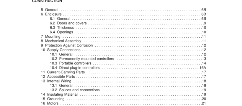
4.1 2 PORTABLE CONTROLLER – A cord connected controller that is mounted by means not requiring a tool for removal and not intended for permanent mounting. 4.1 3 PULSE SEGMENT – A part of a current pulse that is between any two points in time within the duration of the current pulse. 4.1 4 SECONDARY CIRCUITS – Those circuits supplied from transformer output windings that are electrically separated from the input windings. 4.1 5 SINUSOIDAL-DISCHARGE OUTPUT – Output current pulses that are oscillatory current waveforms. 4.1 6 SUPPLEMENTARY (PROTECTING) INSULATION – An independent insulation provided in addition to basic insulation to protect against electric shock in case of mechanical rupture or electrical breakdown of the basic insulation. An enclosure of insulating material may form a part or the whole of the supplementary insulation. 4.1 7 SUPPLY CIRCUIT – The branch circuit supplying electrical energy to the fence controller. CONSTRUCTION 5 General 5.1 A fence controller shall employ materials that are acceptable for the use. 5.2 An enclosure, an opening, a frame, a guard, a knob, a handle, or the like shall not be sufficiently sharp to constitute a risk of injury in normal maintenance or use.
6 Enclosure 6.1 General 6.1 .1 A fence controller shall be provided with an enclosure that, except for the fence terminals, will enclose all uninsulated live parts. The enclosure shall be constructed of metal or polymeric material that complies with the requirements for Polymeric Materials, Section 20. 6.1 .2 The enclosure housing the timing and output mechanism shall be dust and water-resistant as determined by the Humidity and Water-Spray Test, Section 28, and the Hosedown Test, Section 29. 6.1 .3 The enclosure shall be formed so that it will have the strength and rigidity necessary to resist the abuses to which it may be subjected, without resulting in a risk of fire, electric shock, or injury to persons due to total or partial collapse with resulting reduction of spacings, loosening or displacement of parts, or other defects. See 6.1 .4 and 20.5. 6.1 .4 To determine compliance with 6.1 .3, a fence controller shall be subjected to the applicable tests specified in Section 30, Impact Test.UL 69-2009 pdf download.
UL 69-2009 pdf download
