UL 147B-2019 pdf download.Nonrefillable (Disposable) Type Metal Container Assemblies for Butane.
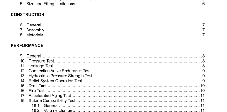
9 General 9.1 Three representative sample of each size and specific construction of metal container assembly and parts constructed of nonmetallic materials are to be subjected to the tests specified in Sections 10 – 18, as appropriate. 9.2 For leakage tests, a source of aerostatic pressure such as air or nitrogen is to be used. 9.3 Water or other liquid of comparable or lighter viscosity may be used for producing the required pressure in a hydrostatic-pressure strength test. 10 Pressure Test 10.1 A representative sample of the metal container assembly shall not leak externally or exceed the pressure limit specified in 4.1 when tested in accordance with 10.2. 10.2 Three metal container assemblies fully charged in accordance with the manufacturer’s production procedures are to be immersed into a water bath maintained at 130°F (54.4°C) until maximum pressure is established. Means are to be provided to monitor the internal pressure of each assembly during this test. 11 Leakage Test 11.1 A representative sample of the metal container assembly shall not show evidence of external leakage at the shutoff valve inlet connection or container joints when subjected to 1-1/2 times the maximum pressure developed under the Pressure Test, Section 10.1, when tested in accordance with 11.2.
12 Connection Valve Endurance Test 12.1 Each type of connection valve assembly shall be subjected to repeated cycles of opening and closing as specified in 12.2. After the endurance test, the valve shall comply with the leakage test requirements specified in 11.1. 12.2 One sample of each different style of valve is to be subjected to a 1500 cycle test conducted in the following manner. The valve is to be connected to a source of aerostatic pressure maintained at 50 psig (345 kPa) for the duration of the test. A mating probe is to be used to depress the valve pin sufficiently to fully unseat the valve poppet and then backed off to close the valve poppet. The rating of cycling shall not exceed 30 cycles per minute. 13 Hydrostatic Pressure Strength Test 13.1 A representative sample of the metal container assembly shall not rupture when tested in accordance with 13.2 and 13.3. A metal container assembly may show evidence of visible deformation or leakage externally during the test sequence. 13.2 Three samples of the metal container assembly without the relief device(s) shall be used. Each sample is to be connected to a source of hydrostatic pressure. A shutoff valve and a calibrated pressure indicating device are to be installed in the pressure-supply piping. The pressure gauge is to be installed in the pressure-supply piping between the shutoff valve and the torch. The samples are to be completely filled with liquid and all air is to be expelled. The pressure indicating device shall comply with one of the following: a) An analog gauge having a pressure range of not less than 1-1/2 times nor more than two times the test pressure; b) A digital pressure transducer, or other digital gauge, that is calibrated over a range of pressure that includes the test pressure; or c) Other device that is equivalent to the devices in (a) or (b). 13.3 The test pressure shall be increased slowly to four times the pressure developed in the Pressure Test, Section 10, and maintained for 1 minute.
15 Drop Test 15.1 Representative samples, fully charged, of the container assembly are to be subjected to the test conditions described in 15.2 and 15.3. If leakage is observed after any of the impacts, the container assembly shall incorporate a cover or cap and be marked in accordance with 20.2. This test is then to be repeated with the cap or cover in place and there shall be no evidence of leakage. 15.2 Three samples, fully charged in accordance with the manufacturer’s recommendations, are to be individually dropped from rest through a vertical distance of 4 feet (1.2 m) onto a concrete surface. One sample each is to be dropped as follows: a) With the height of the container in a perpendicular orientation to the concrete surface such that impact is made on the valve stem or collar. b) With the height of the container at 45 degrees from perpendicular orientation such that impact is made on the edge of the collar. c) With the height of the container at 45 degrees from perpendicular orientation such that impact is made on the edge of the collar opposite (b). 15.3 After impact, each container is to be checked for leakage in a water bath maintained at 130° F (55°C) for 1 minute.UL 147B-2019 pdf download.
UL 147B-2019 pdf download
